Platinum Setup Video
How it Works
The slider in the fleece area has 2 sensor: a top sensor and a bottom sensor. The bottom sensor, which has the white wire, is the main sensor. During normal operation, it should be placed about 1/2″ above the water level in the fleece area. As the fleece gets dirty from catching particulates in the water, it will cause the water level in this fleece area to rise. It will rise up and make the bottom main sensor rise up. When the bottom main sensor moves up, it will turn the motor. As the motor turns, it will bring in new fleece. The new fleece will then make the water level go back down which will make the bottom main sensor go back down and turn off the motor. This process is repeated over and over in small increments keeping the water continuously filtered.
The other two sensors with the black wires are shut off sensors. We used two for redundancy. When either of these black wired shut off sensors move to the up position, it will shut off the motor. This is necessary to make sure the motor does not continuously move when the return pump shuts off (for example when doing a water change). One of theses sensors should be placed in the return pump area about 1/2″ above the normal operating water level. If an ATO unit is used that makes the return pump area water level go up and down over time, then you will want to place the sensor about 1/2″ above the highest water level. The other black wired shut off sensor is located on the slider above the bottom main sensor in the fleece area. This is to shut off the motor in case the water level continues to rise in the fleece area. There is also an emergency opening in the fleece area that will allow the water to empty out into the skimmer/refugium section in case it rises preventing the sump from overflowing.
What’s in the Box
The following shows what is included in each of the 3 accessory bags. Please double check and contact support@triggersys.com if you are missing anything.
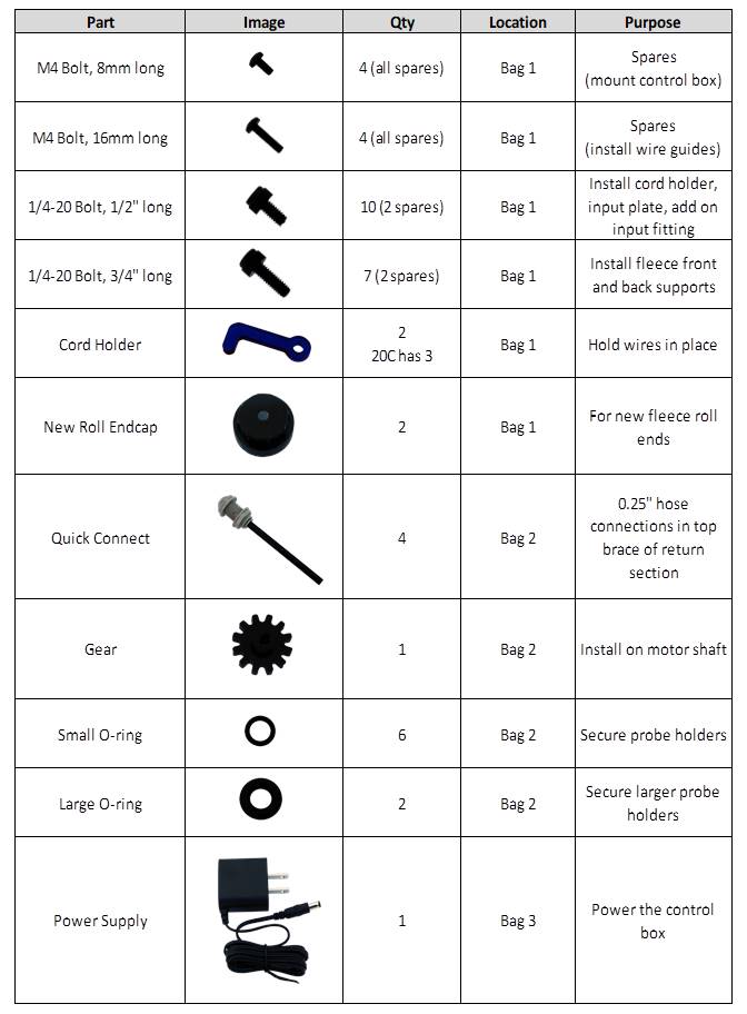
Also included in the box are the following parts:
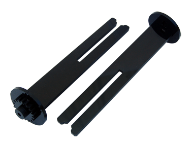
Dirty Holder
Slides together to create the roller that the dirty fleece rolls onto when exiting the sump. When the fleece is used up, simply slide the two parts apart to discard the fleece. Then slide the two parts back together and re-install the dirty holder to roll up the dirty fleece roll as it comes out of the sump.
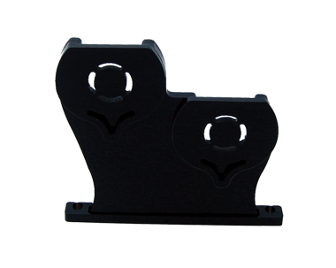
Front Side Support
This piece is mounted towards the front of the sump with the two supplied 1/4-20 bolts that are 3/4″ long. This supports the fleece roll and the dirty holder.
Far Side Support
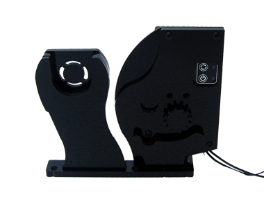
This piece is mounted towards the back of the sump using three 1/4-20 bolts, which are 3/4″ long. The motor control box is connected to this far side support. This piece supports the fleece roll and dirty holder on the far back side of the sump. Both the far side support and front side support have a small amount of play front to back when installing. This is to allow the mounts to be installed so that the fleece sits snug in these supports. The fleece roll and dirty holder should both be snug but not too tight when installed. Tighten the bolts to install the far side support and close side support once they are in position so the fleece roll and dirty holder and snug in these supports. Having too much of a gap may cause the fleece roll to roll unevenly onto the dirty holder. Having it too tight will cause undesired strain on the motor.
Move-able or Removable Middle Wall
This wall is used to divide the middle section, typically into a secion for a refuigum and a section for a protein skimmer. It can be placed anywhere in the middle section so you can set it optimally for your skimmer which will maximize use for the remaining area for a refugium or other filters as needed. When installing the move-able/removable center wall, the bolts that hold this wall in place should be snug. Do not over tighten. Place where desired and then push down and tighten all bolts snug. The sliding cross brace must be placed directly over this wall to ensure the sump will not bow out over time causing this wall to fall out of place. This wall can also be completely removed makign the center section fully open to use as desired. The cross brace should still be placed in the middle of the open section to prevent bowing of the sump over time.
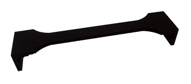
Sliding Cross Brace
The sliding cross brace must be placed directly over the middle wall or in the center of the middle section if the middle wall is not used.
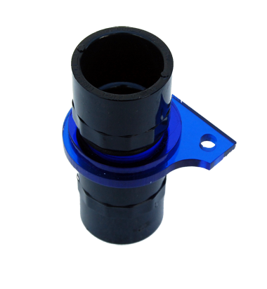
Additional 1″ Input
This additional 1″ input can be placed in the return section or the section right after the fleece area. It is attached to the top brace using two 1/4-20 bolts that are 1/2″ long.
Polycarbonate Lid
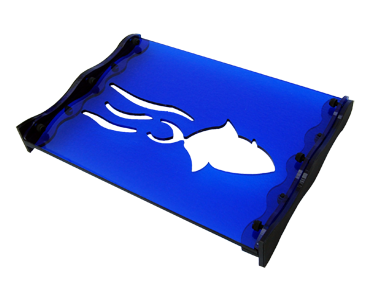
This clear lid is placed over the fleece area to prevent splashing and reduce noise. It come with a white masking to prevent scratches that should be peeled off before installing.
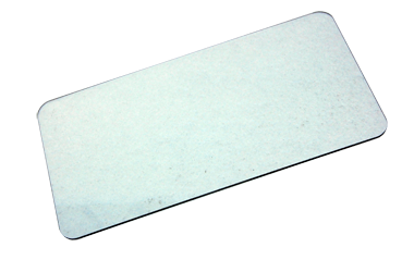
High Flow Plates
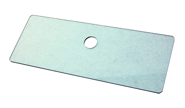
Two of these clear plates are included. These are only needed for high flow applications. These are used to prevent the fleece from being pulled onto the diamond patterns from the back side of the sump. They slide into place along the left side of the sump inside the fleece area.
